|
NUMERICAL ANALYSIS
OF OPTICAL AND ELECTROMAGNETIC PHENOMENA MATLAB EXERCISES:
POLARIZED LIGHT Ian
Cooper matlabvisulaphysics@gmail.com Matlab Script Download Directory op_003.m Animation to show the polarization of light in an XY plane for a light wave propagating in the +Z direction (direction out of the screen, so that you are looking back at the source). The Jones vector parameters A1, B1 and C1 are entered in the INPUT section of the Script. In the CALCULATION section of the Script, the normalized Jones parameters A, B, and C for the Jones vector and the X and Y components of the electric field are calculated. The state of polarization of light is characterised by an elliptical orbit as shown in an animated graphical plot. The animation can be saved as an animated gif file by setting the variable flagS = 1. The Script calls the function arrow.m to draw the electric field vector. op_005.m Animation of electric field vector in space and time. op_004.m Animation of polarized light incident upon optical elements, and the emergent polarized light. The incident polarized light is specified by its Jones Vector and optical elements by their Jones Matrices. The emergent polarized light is given by its normalized Jones Vector. Many of the exercise are based on problems from Introduction to Optics, F.L. Pedrotti and L.S. Pedrotti. Exercise 1 What are the normalized Jones Vectors for each of the following EM waves and give their mode of polarization of each. 1.1
1.2
1.3
1.4
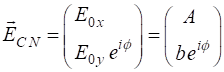
Solution 1 We need to make use of the following
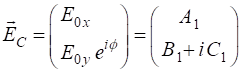
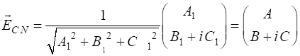
The normalized Jones vector is defined as
where
Given 1.1 linearly polarized at -45o % INPUTS E0x
= 1; E0y
= -1; phi
= 0; % OUPUTS A1
= E0x B1
= E0y * cos(phi) C1
= E0y * sin(phi) N
= sqrt(A1^2 + B1^2 + C1^2) A
= A1/N B
= B1/N C = C1/N A1 = 1
B1 = -1 C1 = 0 N = 1.4142 A = 0.7071 B = -0.7071 C = 0
1.2 linearly polarized at +45o
1.3 right elliptical polarization
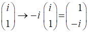
1.4 left circularly polarized
Exercise 2 For each EM wave give its amplitude, propagation direction and mode of polarization. 2.1 2.2 2.3 Solutions 2 You Scripts opLE005.mlx and op_003.m or op_005.m 2.1
Amplitude = 3.00 travelling in +Z direction linearly polarized in X-direction 2.2
Amplitude = 3.61 travelling in +Z direction linearly polarized at 56.3o in X-direction
2.3 Amplitude = 5.00 travelling in +Z direction right elliptical polarized
Exercise 3 Two linearly polarized beans are given by
What is the angle between the two planes of polarization? Solution 3 We can run the Script op_003.m for both
waves and determines the angles of inclination of each electric field vector.
Note the constants
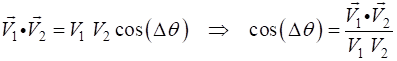
The angle between two vectors can be determined from the dot product of the two vectors
The two vectors for the calculation are the Jones Vector for each EM wave. The calculation can be done using the Live editor Script opLE005.m. The dot product is calculated using the Matlab function dot and the magnitude of a vector is found using the norm function. E10x = 2; E10y = -1; phi1 = 0; E20x = 1; E20y = 4; phi2 = 0; A1 = E10x B1 = E10y * cos(phi1) C1 = E10y * sin(phi1) V1 = [A1; B1+1i*C1] A2 = E20x B2 = E20y * cos(phi2) C2 = E20y * sin(phi2) V2 = [A2; B2+1i*C2] V1dotV2 = dot(V1,V2) magV1 = norm(V1) magV2 = norm(V2) theta = acosd(V1dotV2/(magV1*magV2)) A1 = 2 B1 = -1 C1 = 0 V1 = 2×1 2 -1A2 = 1 B2 = 4 C2 = 0 V2 = 2×1 1 4V1dotV2 = -2 magV1 = 2.2361 magV2 = 4.1231 theta = 102.5288 So, the
angle between the plane of polarization is 102.5o. Exercise 4 A light
beam which is linearly polarized vertically is incident upon a series of
optical elements: a half-wave plate with its fast axis at 45o;
then a linear polarizer with transmission axis at 45o; and then a
quarter-wave plate with its fast axis horizontal. Find the state of
polarization as the light passes through each optical element. Solution 4
op_004.m We need
to take the fast axis of the half-wave plate to be horizontal. So, we can
rotate the half-wave plate by -45o and the rotate the plane of the
incident vertical polarized light also by 45o. After passing
through the half-wave plate, we rotate the plane of polarization through an
angle of +45o. We then consider the linear polarizer with TA at 45o
and then the quarter-wave plate.
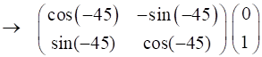
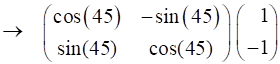
Rotation of vertical polarized light by -45o
Half-wave plate (fast axis horizontal)
Rotate plane of polarization by +45o
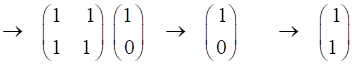
The half-plate oriented at 45o changes the polarization from vertical to horizontal.
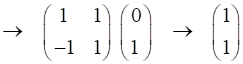
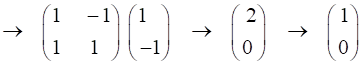
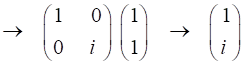
Linear polarizer TA at 45o
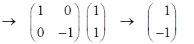
Quarter wave plate (fast axis horizontal)
We can
multiple the Jones Matrices in the Command Window to find the output Jones
Vector: Vin =
[1;0] M1 = [1
1;-1 1] M2 = [1
0;0 -1] M3 = [1
-1;1 1] M4 = [1
1;1 1] M5 = [1
0;0 1i] Vout =
M5*M4*M3*M2*M1*Vin Vout = 2.0000 + 0.0000i
0.0000 + 2.0000i
Exercise 5 State the polarization mode for each of the following Jones Vectors and the amplitude of the electric field. (1) Solution 5
op_003.m
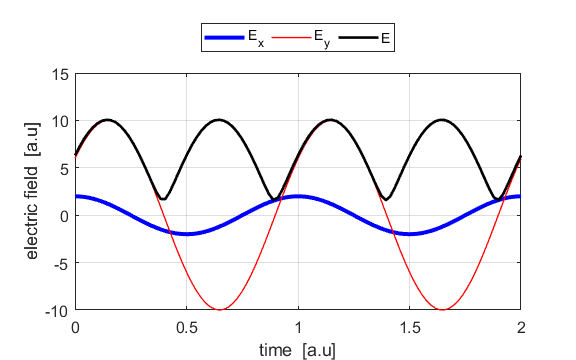
op_005.m (5.1) In
our analysis of polarization, we have taken the X component of the electric
field to real. Therefore, we can multiply the given Jones Vector by
linearly polarized at an angle of 18.4o
amplitude =
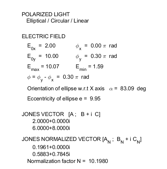
(5.2)
(5.3)
phase difference
Inclination
of ellipse
Using the Script op_005.m
|