|
NUMERICAL ANALYSIS
OF OPTICAL AND ELECTROMAGNETIC PHENOMENA ELLIPTICAL AND
CIRCULAR POLARIZED LIGHT Ian
Cooper matlabvisulaphysics@gmail.com Matlab Script Download Directory op_005.m The Script op_005.m can be used
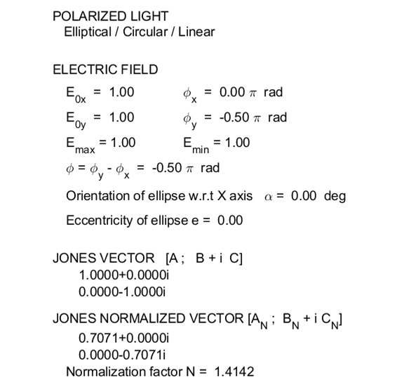
to model the any type of polarization. The animations of the electric field
vector can be saved as animated gif files (flag1 and flag2). In
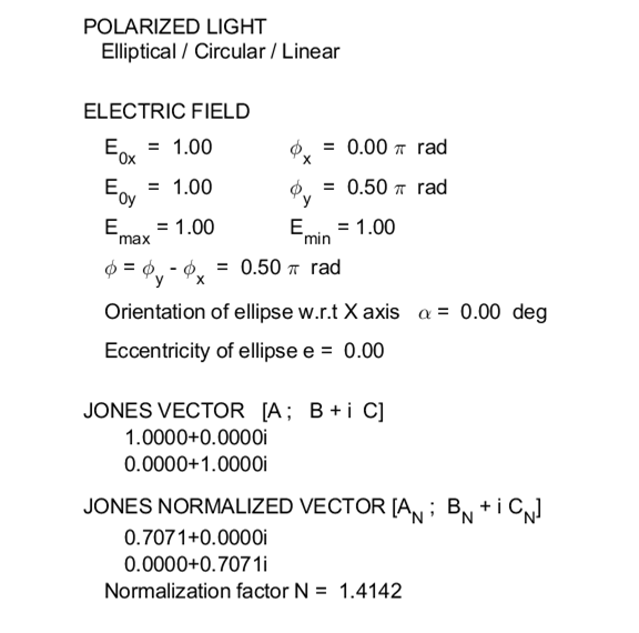
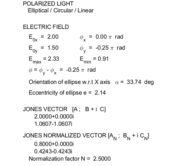
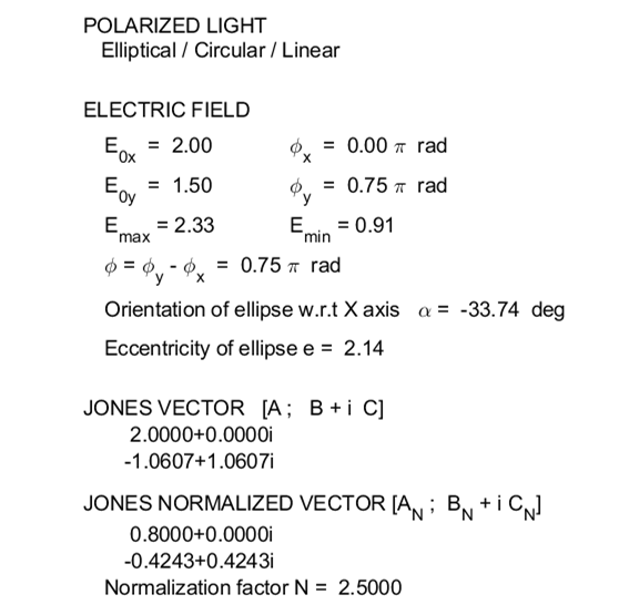
the INPUT SECTION of the Script, you can enter the amplitudes of the electric
field components and their phase angles (flagP = 1) or
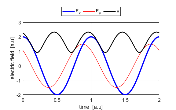
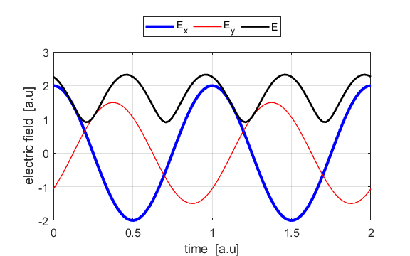
the Jones parameters (flag2 = 2). From the input values, the electric field (E,
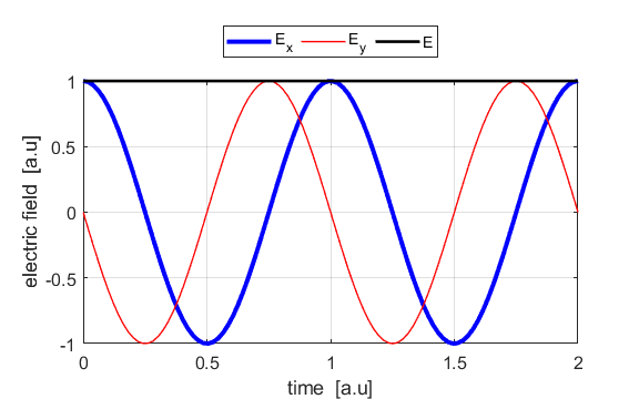
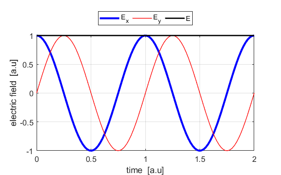
Ex, Ey) as functions of time t and position z are
calculated. In any plane (z = constant), the electric field vector sweeps out
an ellipse with time, a straight line (linear polarization) and a circle
(circular polarization) are special cases of an ellipse. The time evolution
of the magnitude of the electric field is used to find its maximum Emax and minimum Emin values
and the angle POLARIZED LIGHT From a mathematical point of view, both
linear and circular polarized light may be considered to be special cases of
elliptical polarized light. In general, for elliptical polarized light, the
electric field vector will change magnitude as it rotates. In such cases, the
endpoint of the electric field will trace out an ellipse in any XY plane when
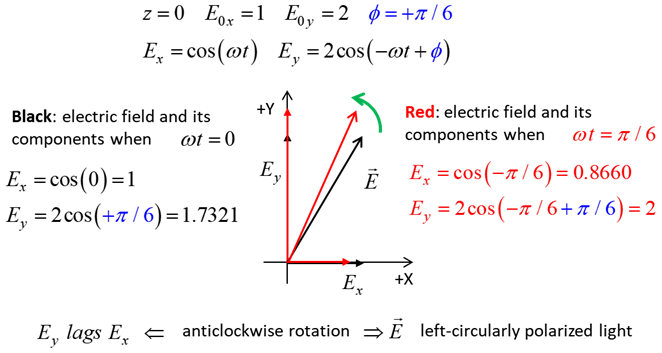
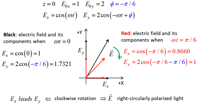
the EM wave propagates in the Z direction. The semimajor axis makes an angle Consider the example where and take the two times such that
Fig. 2A. Left-polarised
light - positive helicity
Fig. 2B. Right-polarized light - negative
helicity
The state of polarization depends upon the relative phase The
animations show the time evolution of the electric field and its components
for different values of the relative phase angle
CIRCULAR POLARIZED LIGHT The conditions for circular polarization are:
Right circular
polarized light
For a fixed value of t,
the electric field vector describes a spiral on the surface of a cylinder of
radius Left circular polarized light
ELLPTICAL POLARIZED LIGHT Right Elliptical
polarized light
Left Elliptical
polarized light
|