|
NUMERICAL ANALYSIS
OF OPTICAL AND ELECTROMAGNETIC PHENOMENA OPTICAL ELEMENTS
AND THE MANIPULATION OF THE STATE OF POLARIZATION Ian
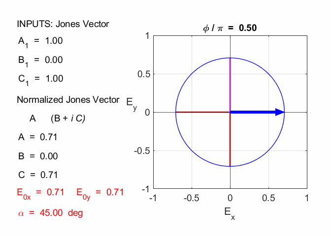
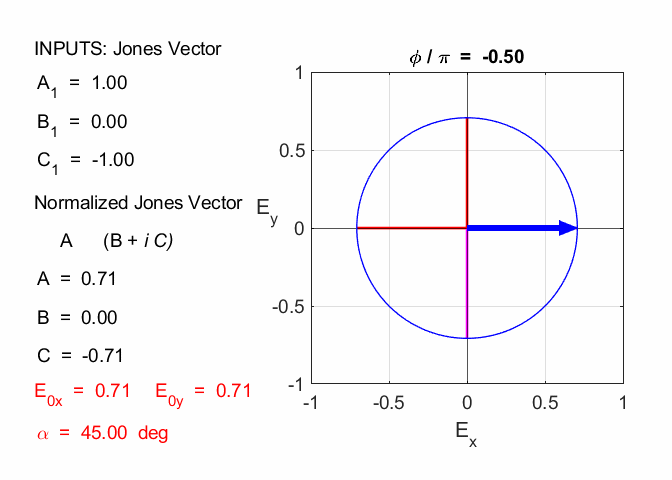
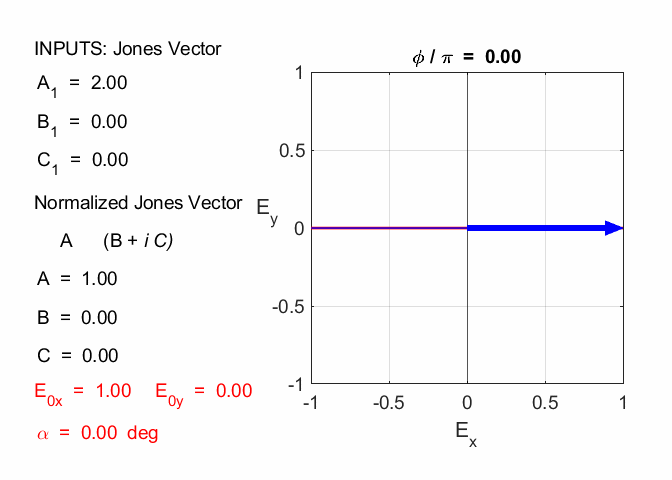
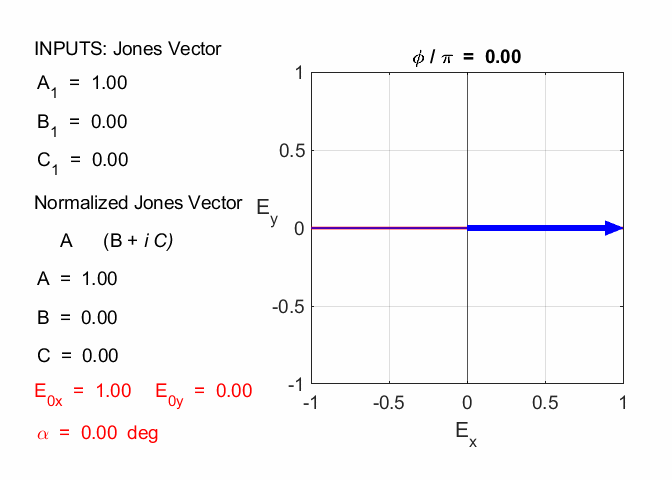
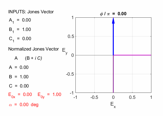
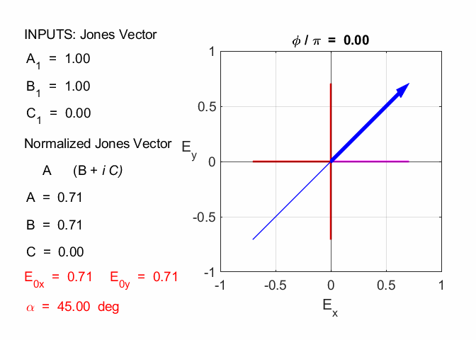
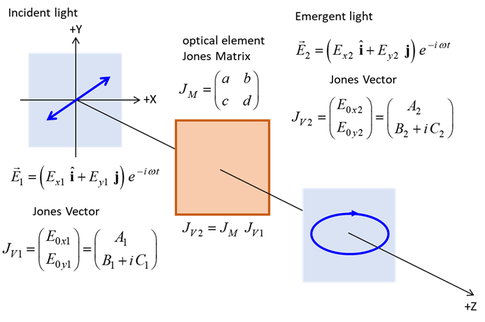
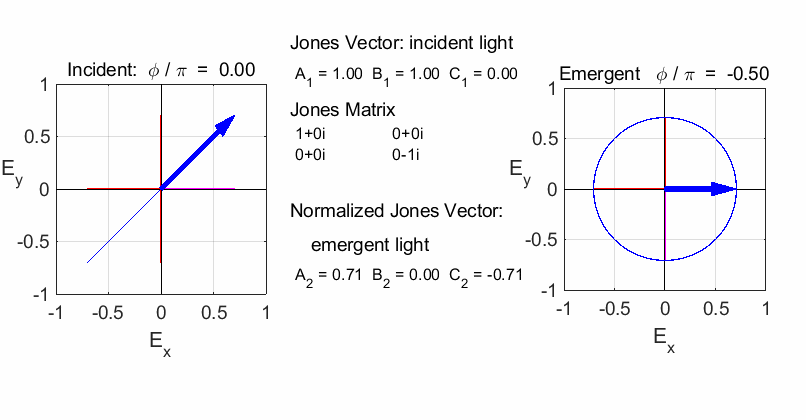
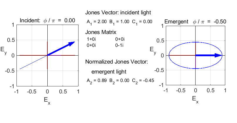
Cooper Matlab Script Download Directory op_003.m Animation to show the polarization of light in an XY plane for a light wave propagating in the +Z direction (direction out of the screen, so that you are looking back at the source). The Jones Vector parameters A1, B1 and C1 are entered in the INPUT section of the Script. In the CALCULATION section of the Script, the normalized Jones parameters A, B, and C for the Jones Vector and the X and Y components of the electric field are calculated. The state of polarization of light is characterised by an elliptical orbit as shown in an animated graphical plot. The animation can be saved as an animated gif file by setting the variable flagS = 1. The Script calls the function arrow.m to draw the electric field vector. op_005.m Animation to show the polarization in a XY plane and the spiral path of the time evolution of the electric field along the Z axis. op_004.m Animation of polarized light incident upon optical elements, and the emergent polarized light. The incident polarized light is specified by its Jones Vector and optical elements by their Jones Matrices. The emergent polarized light is given by its normalized Jones Vector. JONES VECTORS The Jones Vectors gives another representation of
polarized light. The usefulness of Jones
Vectors will be demonstrated after we have developed the Jones Matrices which represent polarizing optical elements. The state of
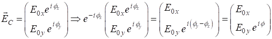
polarization of light is completely determined by the relative amplitudes and
relative phase of the components
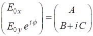
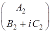
The X component element of the Jones Vector is taken as a real quantity and we can always multiply the column vector by suitable quantity to achieve this, since the state of polarization depends only upon the relative amplitudes. The multiplication of the column vector by a constant does not change the state of polarization angle. The most general case for the Jones Vector is expressed as
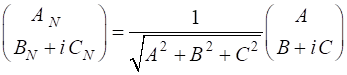
where A, B and C are real constant. The normalized Jones
Vector is defined such that
So, given the Jones Vector expressed in terms of A,
B
and C we can calculate the electric field
components and the relative phase
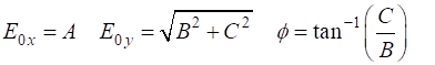
or given the electric field components, we can calculate
the Jones parameters A, B
and C Summary of several types of polarization given by the normalized Jones Vector linearly polarized along X
direction
linearly polarized along Y direction
linearly polarized at an angle
left circularly polarized
right circularly polarized
SUPERPOSITION By adding the Jones Vectors, we can calculate the result of the superposition of two or more polarized modes using the Script op_003.m. For example, consider the addition of left- and right-circular polarized light that have equal amplitudes (figure 1).
Fig. 1. The addition of the left- and right-circularly polarized light with equal amplitudes results in light of horizontal linear polarization. We can conclude that linearly polarized light can be regarded as being composed of left- and right-circularly polarized light with equal amplitudes. Another
example, the superposition of vertically and horizontally linearly polarized
light with equal amplitudes and oscillating in-phase, results in linearly
polarized light inclined at an angle of 45o.
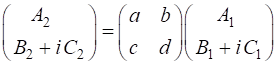
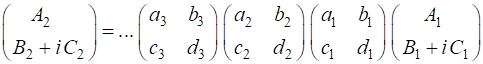
Fig. 2. The superposition of horizontal and vertical polarized light with equal amplitudes and oscillating in phase is found by simply adding the Jones Vectors. The result is linearly polarized light at 45o inclination. JONES MATRICES FOR LINEAR OPTICAL ELEMENTS It easy to calculate the effect of inserting a linear optical element or a train of optical elements into a beam of light of given polarization by using Jones Vectors and the Jones Matrices. The optical elements are represented by 2x2 matrices called the Jones Matrices. The matrices are used as follows. The Jones Matrix for an optical element is of the form
Let the incident light be given by the Jones Vector
and the vector of the emerging light be
such that
If the light is sent through a train of optical elements, then the result of the matrix multiplication is
Fig. 3. The Jones Matrix acts as a transfer function to convert the polarization of the incident light (input) to the polarization of the emergent light (output). The
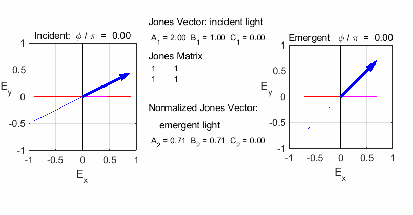
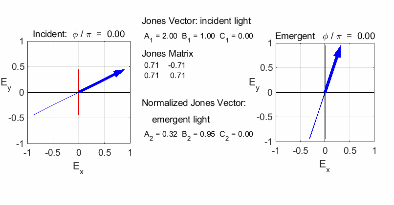
Script op_004.m is used to
calculate the polarization of the light after passing through a linear
optical element represented by a 2x2 Jones Matrix. The polarization of the
incident light is given by a Jones Vector and the emergent light given by a
normalized Jones Vector. The animated plot shows the normalized electric
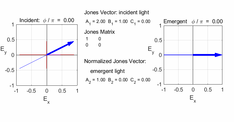
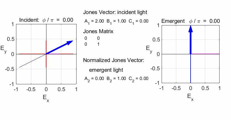
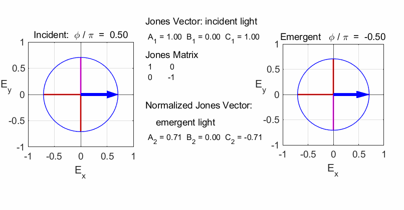
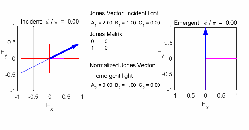
fields for the incident and emergent polarized light. LINEAR POLARIZERS Selectively removes all or most of the electric field vibrations except in the direction of the transmission axis of the linear polarizer. X-polarizer:
horizontal transmission axis
Y-polarizer:
horizontal transmission axis
45o
transmission axis
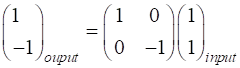
ELLIPTICAL
POLARIZERS Incident linear polarized light is transmitted from the optical element as elliptical polarized light. right
left
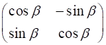
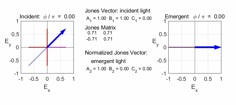
ROTATOR This element has the effect of rotating the direction of
polarization of the light incident upon it by the angle % Rotator beta = 45; a = cosd(beta);
b = -sind(beta); c = sind(beta);
d = cosd(beta);
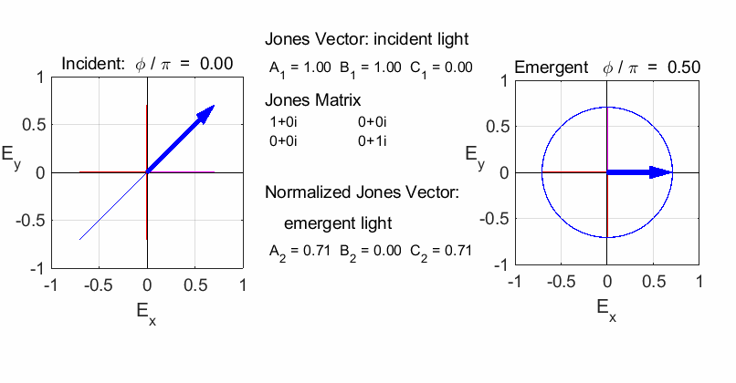
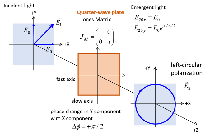
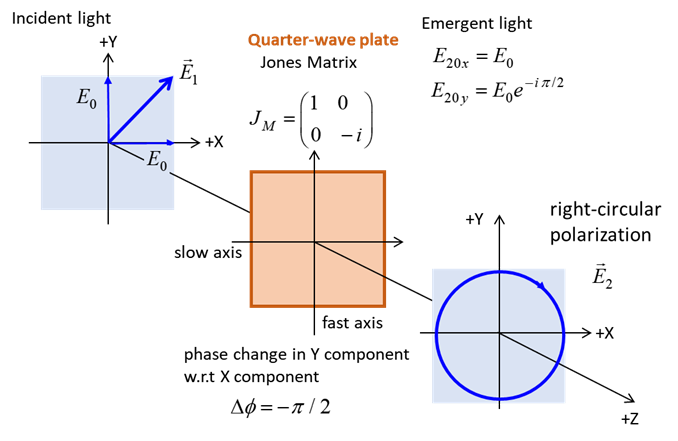
QUARTER-WAVE PLATE Circularly polarized light can be produced by introducing
a phase shift of
The fast axis of the quarter-wave plate is aligned along
the X-axis (horizontal) or Y-axis (vertical). To convert linear polarized
light into circularly polarized light, the incident light must be aligned at
an angle of 45o
or 135o
with respect to the fast axis (or slow axis). Hence, the light entering the
quarter-wave plate can be resolved into two orthogonal linearly polarized
components of equal amplitude and phase. On emerging from the quarter wave
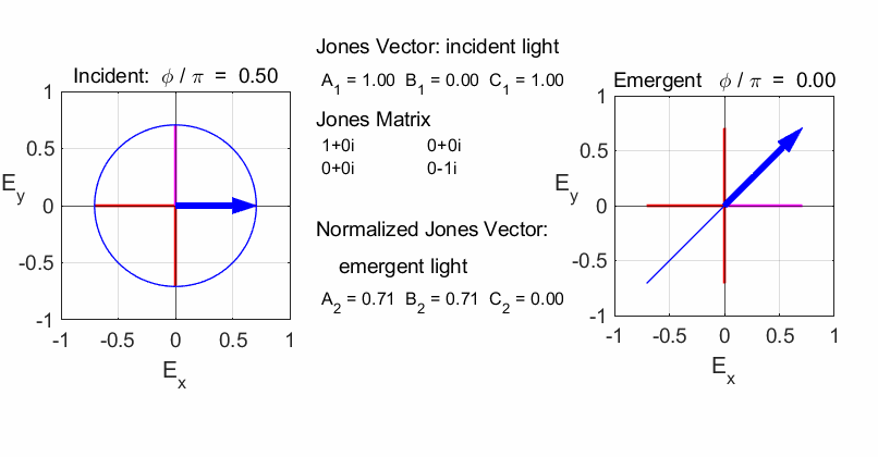
plate, the two components will be LEFT circular
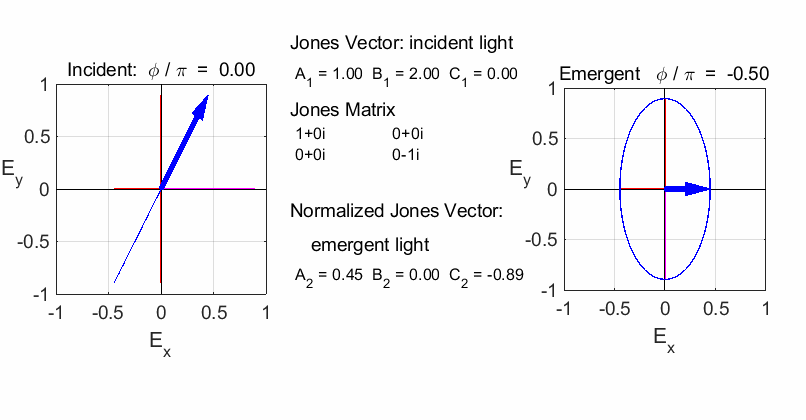
polarized light / fast axis horizontal
RIGHT circular
polarized light / fast axis
vertical
RIGHT elliptical
polarized light / fast axis vertical
Note: change in orientation of ellipse in the previous two animations. If the incident light is circularly polarized, then the emergent light will be linearly polarized
fast axis vertical
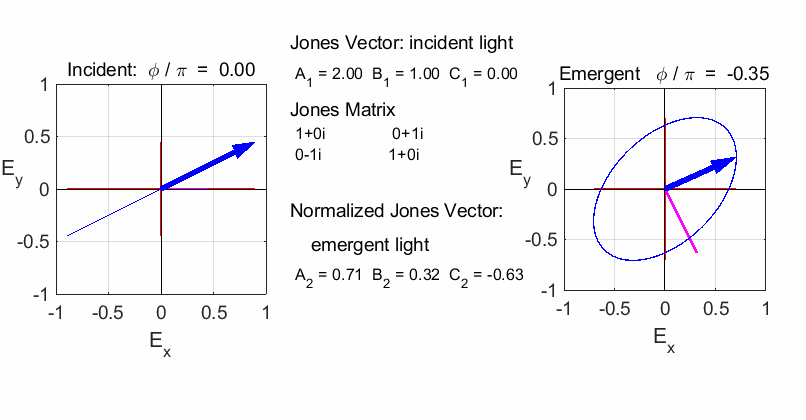
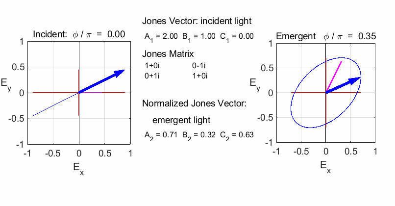
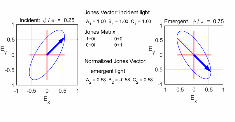
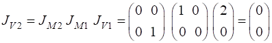
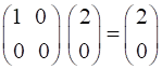
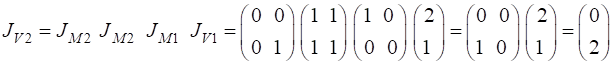
Elliptical to
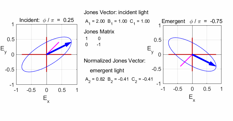
elliptical with a rotation of the major axis of the ellipse If the incident light is elliptical polarized, then the
emergent light is also elliptical polarised with a rotation of its axis. For
example:
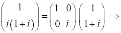
Incident Jones Vector
Jones Matrix
Emergent Jones Matrix
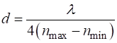
HALF-WAVE PLATE The thickness d of a half-wave plate is
The Jones Matrix when the fast axis aligned along the X
axis is
The half-wave plate will have the effect of changing the polarization from right to left and vice versa.
For incident elliptical polarized light on the half-wave plate, the emergent elliptical polarized light will be flipped, and the sense of rotation reversed.
A half-wave plate can be made by passing light through two quarter-wave plates
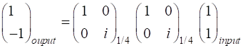
A half-wave plate is very handy in rotating the plane of polarization from a polarized laser to any other desired plane. Most large ion lasers are vertically polarized, for example, so to obtain horizontal polarization, simply place a half-wave plate in the beam with its fast (or slow) axis 45° to the vertical. CROSSED-POLARIZERS Consider the incident light to be linear polarized horizontally and given by the Jones Vector A = 2, B = 0, C = 0
The light passes through an X polarizer The emergent light is given by
Hence, no light passes through the cross-polarizers. We now can place another polarizer between the cross-polarizers which produces light that is linear polarized with its transmission axis inclined at 45o w.r.t to X axis. This now leads to light emerging from the optical elements which is polarized in the Y direction.
The normalized Jones Vector for the emergent light is
|