|
COMPUTATIONAL NEUROSCIENCE THE NEURON MEMBRANE AS A CAPACITOR Ian Cooper Any comments, suggestions or corrections, please email me at |
|
MATLAB DOWNLOAD DIRECTORY FOR SCRIPTS simpson1d.m (function: integration using
Simpson’s rule) RC01.m (RC circuit: charging a capacitor) RC02.m (RC circuit: discharging a capacitor) RC03.m (RC circuit: step or pulse current input) |
|
INTRODUCTION Many electronic circuits use combinations of
resistors and capacitors for controlling the timing of events. For example,
the flash unit in a camera: typically there is a delay before taking a flash
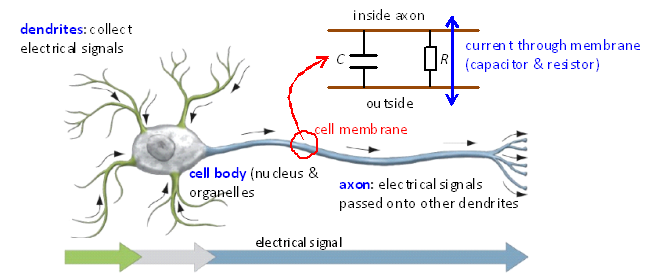
picture because of the time required to charge the capacitor. In a nerve cell called a neuron, currents can pass through the cell membrane
from inside to out or from outside to in. Inside and outside the neuron is an
electrolytic fluid which is a good conductor and the membrane acts as a
dielectric (insulator) separating the two electrolytes. Thus, the simplest model of a segment
of the neuron membrane is a capacitor and resistor connecting the outside to
the inside of the cell.
Fig.
1. The membrane of a neuron
can be modeled as a combination of a resistor and a capacitor. To understand the transient
effects in RC circuits and to start thinking about how signals are propagated
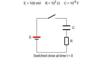
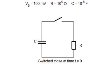
along nerve cells, models of RC circuits will be developed. CHARGING A CAPACITOR RC01.m Let a capacitor C and resistor R be connected in series to a battery of emf
E via a switch. At time t = 0, the switch is closed and
initially the capacitor is uncharged.
Fig. 2. RC circuit diagram used to charge the capacitor. Variables and default values E = 100 mV battery emf R = 103 W resistance (typical neuron membrane
resistance value) C = 10-6 F capacitance (typical
neuron membrane capacitance) t = R C = 10-3 s = 1.00 ms time
constant (tau). For nerves: time
constants ~ ms VC potential
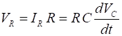
across capacitor [V] VR potential
across resistor [V] Q charge
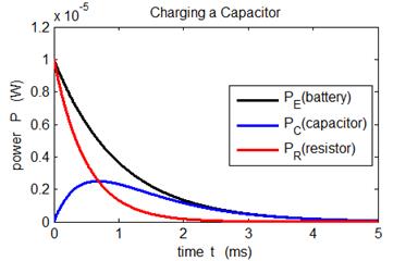
on plates of capacitor [C] I = IR = IC current [A] PE power
supplied by battery [W] PC power
stored by capacitor [W] PR power
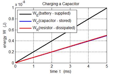
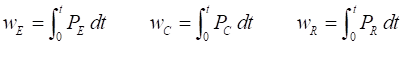
dissipated by resistor [W] wE energy
supplied by battery [J] wC energy
stored by capacitor [J] wR energy
dissipated by resistor [J] Derivations From
Kirchhoff’s voltage law, we can write the differential equation for VC and solve it to find all
the parameters that describe the RC circuit. Kirchhoff’s
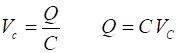
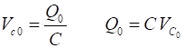
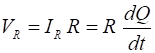
voltage law Voltage and charge stored by capacitor
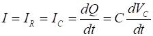
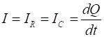
Current (series circuit)
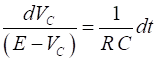
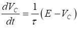
ODE to solve (from Kirchhoff’s voltage law) Solution of ODE
with initial conditions t =
0 and VC = 0
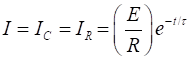
From the solution VC Current
Charge Power
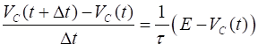
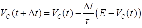
Energy (integration by Simpson’s rule) The ODE for VC
can also be solved using the finite difference
method. ODE to be solved Finite differences approximate the derivative ( Solve starting with t = 0 and VC(0)
= 0 Graphical Predictions RC01.m
Fig.
3. When the switch is
closed, exponential changes occur in the potential across the
capacitor C and the resistor R. The applied potential difference E at all times is the sum of the
potential difference across the capacitor VC
and resistor VR (E = VC + VR).
As soon as the switch is closed: VC
= 0 and VR = E. In a time of one time constant t = RC
the capacitor potential VC increases by 63% of its final value and
the potential across the resistor VR
drops by 63% to 37% of its initial value. If a membrane is suddenly allowed to charge
passively to a new membrane potential, the time course of the voltage is
exponential and undergoes 63% of the total change in about 1 ms.
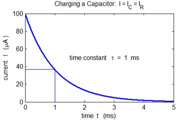
Fig. 4. When the switch is closed, the
current decreases exponentially. In a time of one time constant t = RC the
current (I = IC = IR) in the circuit drops by 63% to 37% of its
initial value. Once fully charged, a capacitor in a DC
circuit acts like an open switch in the branch in which it is placed. This
property is used in many electronic circuits to remove a DC voltage component
of a signal.
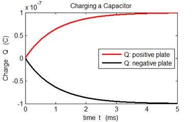
Fig. 4. When the switch is closed, the
capacitor is charged as the charged stored on the two plates increases as an
exponential function. The curve for the charge is identical in shape to the
potential difference across the capacitor as Q
µ VC.
For t > 5t, the capacitor can be considered fully charged.
Fig. 5. The battery supplies the energy
in the circuit. Some of this energy is stored by the capacitor and the
remainder of the energy is dissipated as internal energy by the
resistor’s current (Ohmic losses).
Fig. 6. The battery supplies the energy
in the circuit. Some of this energy is stored by the capacitor and the
remainder of the energy is dissipated as internal energy by the
resistor’s current (Ohmic losses). The energy stored by the capacitor
at all times in equal to half the energy dissipated by the resistor (WC
= WR). The energy
stored by the capacitor is given by which
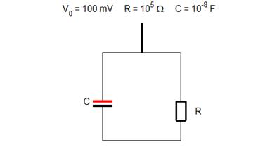
agrees with the prediction of our model. DISCHARGING A CAPACITOR RC02.m Let a capacitor C
and resistor R be connected in
parallel to each other and with no connection to a source of emf. At time t
= 0, the switch is closed and initially the capacitor is fully charged.
Fig. 7. RC circuit diagram used to discharge
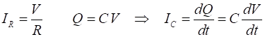
the capacitor. Derivations From Kirchhoff’s voltage
law, we can write the differential equation for VC and solve it to find all the parameters that
describe the RC circuit. Kirchhoff’s voltage law Voltage and
charge stored by capacitor Initial
values t = 0 V0 = 100 mV Current
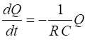
(series circuit) ODE to solve
(from Kirchhoff’s voltage law) Solution of
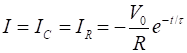
ODE with initial conditions t = 0 and Q0 = VC0 From the
solution Q Current Power Energy
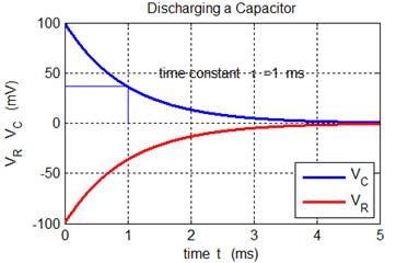
(integration by Simpson’s rule) Graphical Predictions RC02.m
Fig.
8. When the switch is
closed, exponential changes occur in the potential across the
capacitor C and the resistor R. At all times is the sum of the
potential difference across the capacitor VC
and resistor VR is zero
(VC + VR = 0). As soon as the
switch is closed: VC = +100 V and the voltage
drop across the resistor is VR
= -100 mV. In a time of one time constant t
= RC the capacitor potential VC
and resistor potential VR
magnitudes decreases to 37% of their initial values.
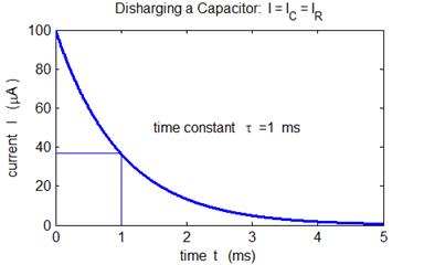
Fig. 9. When the switch is closed, the
current decreases exponentially. In a time of one time constant t = RC the
current (I = IC = IR) in the circuit drops to 37% of its initial
value.
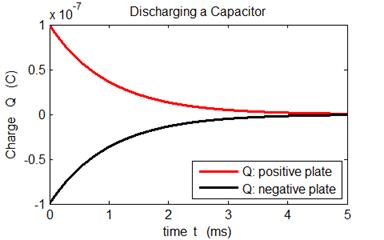
Fig. 10.
When the switch is closed, the capacitor is fully charged as the
charged stored on the two plates then decreases as an exponential function.
The curve for the charge is identical in shape to the potential difference
across the capacitor as Q
µ VC.
For t > 5t, the capacitor can be considered fully discharged.
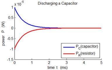
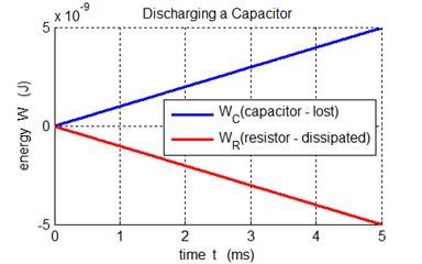
Fig. 11. The energy initially stored by
the capacitor is dissipated as internal energy by the resistor’s
current (Ohmic losses).
Fig. 12. The energy is stored by the
capacitor is lost as internal energy by the current in the resistor. TRANSIENT RESPONSE: STEP (PULSE) CURRENT
INPUT RC03.m The capacitor C and resistor R are
connected in parallel and a current is injected into the circuit as shown in
figure 13.
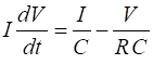
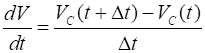
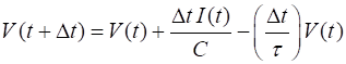
Fig. 13. RC circuit diagram for current injection. Derivations Capacitor and resistor connected in parallel Kirchhoff’s current law: I is the injected current Conservation of charge Currents ODE to be solved for V The easiest way to solve this ODE
is to use the finite difference
method where the derivative is replaced by a difference
equation: Good approximation provided dt << t = RC Can find successive values of V in time steps Dt
Charge at time t Currents at time t
Graphical Predictions RC03.m
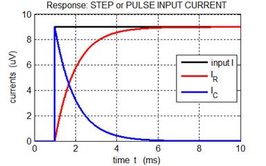
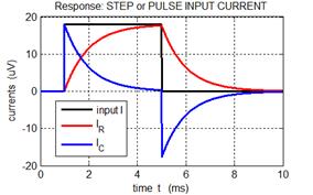
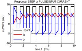
Fig. 14. Variation in the currents as
functions of time. I is the external current injected into the circuit. The
resistive current IR
and capacitive current IC
vary exponentially with a characteristic time constant t = R
C = 1 ms. When the input current I jumps, the capacitor charges almost
immediately then discharges through the resistor R, while the capacitive current IC decreasing exponentially. The resistive current
increases exponentially to a maximum level after a time interval of about 5t.
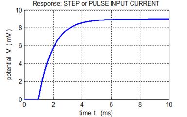
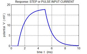
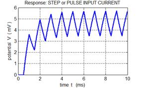
Fig. 15. The voltage across the parallel
combination of R and C increases exponentially to a maximum
level with a characteristic time constant t = R C
= 1 ms.
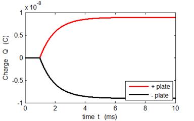
Fig. 16. The charge Q on the plates of the capacitor C increases exponentially to a maximum level with a
characteristic time constant t = R
C = 1 ms. The shape of the curve is the
same as the variation in voltage since
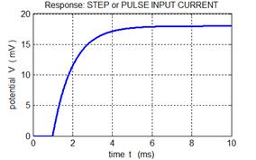
Fig. 17. When the magnitude of the step
current increases by a factor of 2, then the change in the maximum potential
difference also doubles.
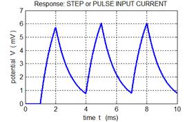
Fig. 18. Response for a pulse input. The
capacitor charges then discharges. The potential difference V curve is the same shape as the curve
for the resistive current IR since IR µ V.
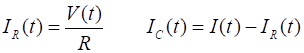
For a neuron, at any instant, the total
current I(t) is equal to the sum of the
currents through the membrane: I(t)
= IC(t) + IR(t) where IR(t) is a conducting current and IC(t) is known as a displacement
current. The current thus depends upon the voltage and the rate of
change of the voltage and this parallel combination offers minimum opposition
to current for rapidly changing voltages since there is not enough time for
the capacitance to charge significantly.
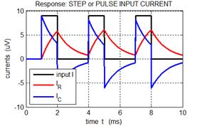
Fig. 19. Response for a series of pulses.
For a rapid series of pulses the conductive current IR has small
fluctuations about an average value. The result of many pulses arriving at a
neuron is that the voltage across the membrane can grow as the capacitor
charges and discharging. This can result is a sufficient voltage across the
membrane to produce an action potential (large voltage spike) then can
initiate the propagation of a signal along the axon. |