|
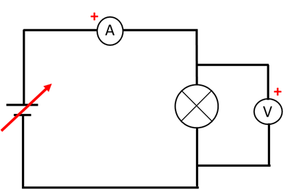
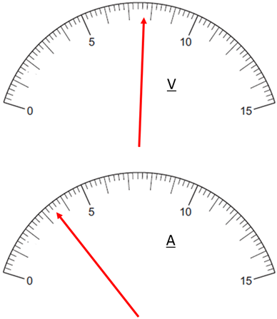
VISUAL PHYSICS ONLINE 4.1 ELECTRICITY P41 009 You are supplied with a variable 12 V DC power supply, an ideal ammeter, an ideal voltmeter, a 12 V lamp and electrical leads. (A) Draw a circuit diagram using the components listed above so that you could measure the resistance of the lamp and power supplied to the lamp. (B) Describe an experiment you could perform to measure the resistance of the lamp as a function of lamp current. (C) When the circuit was correctly wired, the two meters give the readings shown below. What is the resistance of the lamp and power being dissipated by the lamp?
View solution below only after you have completed the answering the question. |
|
|
|
Solution (A) (B) Vary the power supply voltage from 0 to 12 V and for each
voltage record the ammeter (C) voltameter reading ammeter reading resistance
power
|