|
VISUAL PHYSICS ONLINE 6 ELECTROMAGNETISM P60 017 Consider the generator
shown in the diagram with the parameters magnetic field B
= 1.25 T LCD = LEF = 12 mm
LDE = LCF = 6.0 mm Rotation rate Number of turns of coil N = 100 Total resistance of coil Rcoil = 10 W Resistance of external load connected between A and B Rload
= 125 W
(A)
Calculate:
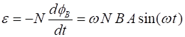
Angular frequency w =
? rad.s-1
Frequency of rotation
f = ?
Hz
Period of rotation T
= ? s
Maximum magnetic flux fB = ? T.m2
Maximum induced emf (polarity of point A
w.r.t to the point B)
emf
= ? V
Maximum induced current in the circuit I
= ? A (B)
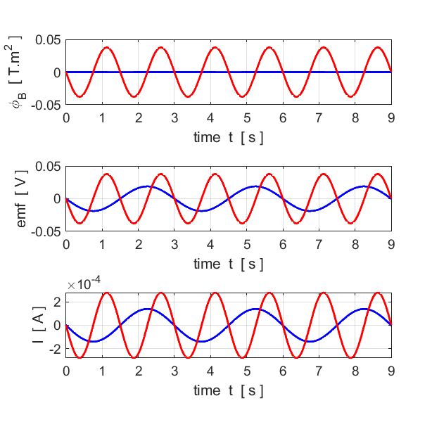
Sketch the time graphs for the quantities: magnetic flux; induced emf; induced current. (C)
On your graphs add curves to show the resulting changes that would
occur if the rotation speed was doubled. The generator is now to be used a
motor. The coil is no longer rotated by an external mechanical energy supply
and the load is removed from between A and B. The point A was connected to the
positive terminal of a 12 V battery and point B was connected to the negative
terminal. (D) Explain why this arrangement
does not work as a motor. (E)
The commutator of the slip rings is replaced by a split ring. The
motor now works. Why? View solution below only after you have completed the answering the question. |

|
Solution LCD = LEF = 12 mm = 12´10-3 m LDE = LCF = 6.0 mm = 6´10-3 m Magnetic field B = 1.25 T Rotation rate = 20 rpm (revolutions per minute) Number of turns of coil N = 100 Total resistance of coil Rcoil = 10 W Resistance of external load connected between A and B Rload = 125 W (A) w = 20 rpm = (20)(2p) / (60) rad.s-1 = 2.09 rad.s-1
area of coil rotating in magnetic field A = (12´10-3) (6´10-3 m) = 72x10-6 m2 Rtotal = Rcoil + Rload = (10 + 125) W = 135 W
(B) (C)
As rotation rate increase Þ increase in induced emf Þ increase in current Þ greater force opposing rotation of coil Þ counter torque (D) (E)
|