|
KINEMATICS
[2D] MOTION IN A PLANE
We will consider the two-dimension motion of objects moving in a
plane with a uniform
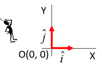
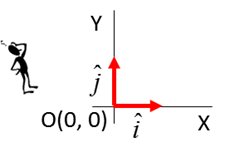
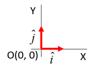
acceleration. Again, the first step is define a frame of reference
Observer Origin O(0,0, 0) reference
point Cartesian
coordinate axes (X,
Y, Z) Unit
vectors Specify
the units The
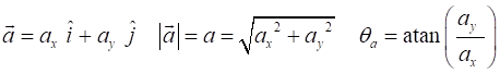
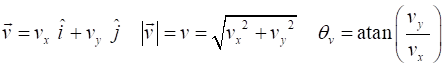
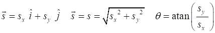
equations for the [2D] motion of an object moving in a plane are acceleration velocity displacement These
vectors equations are not very useful. It is much better to express the
equation for [2D] motion in terms of the X and Y components of each vector. Remember
a vector component is a scalar quantity. When
the object is moving with a uniform (constant) acceleration, the
equations describing the motion for the time interval time acceleration
velocity
displacement
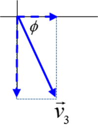
The angles
N.B. subscripts 1 and 2 denote the
time for Event #1 and Event #2 and We will consider the [2D] motion in a plane
called projectile
motion. When studying Physics, one key to becoming successful is
being able to visualize a physical phenomenon. So, “make an effort”
to visualize the flight of a thrown ball, a golf ball and a tennis ball.
Now Physics is not about the real-world. A Physicist
looks at a physical phenomenon and makes a set of approximations and simplifications
to develop a mathematical model that can be used to make predictions. These predictions
are then compared to the real-world measurements to test the validity of the
mathematical model. The simple model is often expanded by adding complexities
to given a better model of the real-world situation. In developing our model of the flight of a ball,
we need to make lots of approximations and simplifications. The ball is
identified as our system (point particle) and is represented as a dot in a
scientific diagram. We ignore the action of throwing or catching the ball and
ignore any contacts with an obstacle e.g. our ball does not hit the ground. We
are only interested in the flight of the ball. Assume that the ball only moves in a vertical
plane and ignore any friction effects or effects of the wind.
The acceleration is assumed to be constant (does
not change with time) such that
Event #1 gives the initial values for the time,
velocity and displacement of our system and Event # 2 gives the final values
for time, velocity and displacement. Exercise
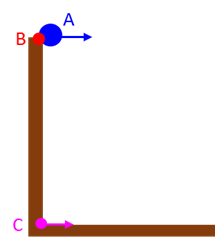
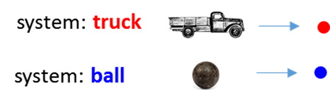
System
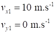
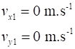
A 10 kg blue ball System
B 5 kg red ball System
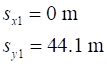
C 1 kg magenta ball Event #1 ( The
three balls are launched simultaneously as shown in the diagram and the initial
values are displayed in the table.
Event #2
( The
time interval for the motion of the balls is 3.0 s. A.
Visualize the motion of the three
balls. On a single diagram, sketch for the trajectory for each ball. B.
What the final values for the
acceleration, velocity and displacement after 3.0 s? Give the values for the components,
magnitudes and directions. C.
For each ball, draw a series of
graphs to show the variation with time in the 3.0 s interval for: the
trajectories; acceleration components; velocity components and displacement
components. How do your predictions agree with the
trajectories displayed in the simulation?
D. What can you conclude about the independence of
the motions in the horizontal (X) and vertical (Y) directions? Continue only after you have completed questions A to D Carefully compare your results with the following answers and
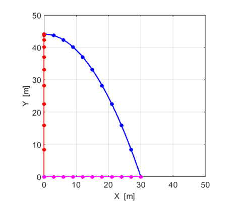
resolve and any discrepancies Figure (1) shows the trajectories of the three particles: System
A 10 kg blue ball System
B 5 kg red
ball System
C 1 kg magenta
ball The solid curves show the paths for the three balls. The coloured
dots show the positions of the balls at 0.30 s intervals.
Fig. 1. The trajectories of the three
balls. The blue
(A) and red (B) balls have identical vertical motions. The blue
(A) and magenta (C) balls have
identical horizontal motions. The horizontal motion and vertical motion are independent of each
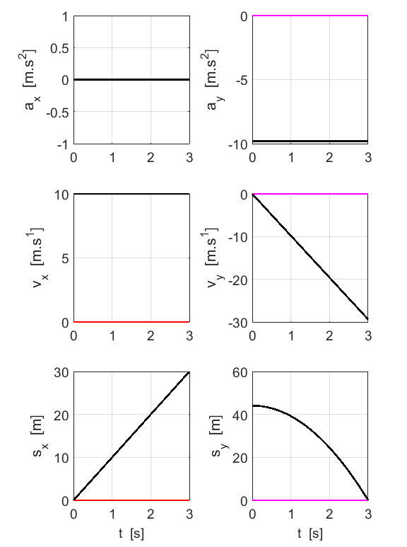
other. The motion of a ball does not depend upon its mass. Figure (2) show the variation in the components of the acceleration,
velocity and displacements as functions of time. The colour of the line
identifies the ball (A blue, B red, C magenta). If two or more of the results
for the graph are the same, the colour is shown as black.
Fig. 2. Time evolution of
the acceleration, velocity and displacement.
EXERCISE
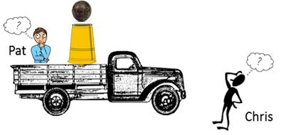
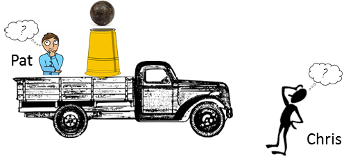
One person said that the cannon ball went straight up into the air
while another person said that the cannon ball followed a parabolic path. Surely, both people cannot be correct !!! What is you view on the motion of the cannon ball? Think about the physical situation carefully and visualize the motion
of the ball. Setup a model so that you can make predictions about the
ball’s motion. Make a list of the physical quantities of interest that you can
calculate. Remember there are two observers – Pat and Chris. Make a list of the approximations and simplifications necessary to
make your numerical predictions. Calculate the numerical values of the quantities in your list. Show a set of graphs illustrating the motion of the ball. Continue only after you have completed all the above mentioned
tasks Carefully compare your results with the following answers and
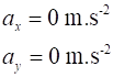
resolve and any discrepancies Approximation and Simplifications Assume that the velocity of the truck is constant and travels on a
level road. We are concerned only with the flight of the cannon ball and
ignore the firing or landing of the cannon ball. Assume that the ball only
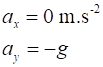
travels in a vertical plane and ignore any frictional effects. The acceleration is assumed to be constant (does
not change with time) such that The physical situation is complicated. We have two observers (Pat and
Chris) and two systems (truck and the cannon ball). Think about the situation by visualizing it. We can conclude that
from Pat’s point of view the truck remains stationary and the ball goes
up and down. Chris’ s point of view is that
the truck moves with a constant velocity and the ball also goes up then falls. To simplify the situation, we identity two systems and two frames of
reference.
Frame of reference
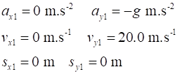
Event #1 ( Event #2 (
Pat’s frame of
reference: Initial values
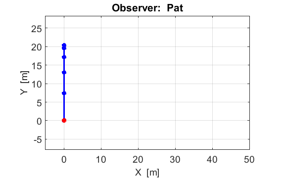
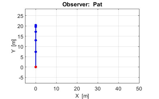
Figure
(3) shows the motion of the truck and the cannon ball from the frame of reference of Pat.
In Pat’s frame of reference the truck does not move while the ball
rises as it slows down and stops at its maximum height and falls with
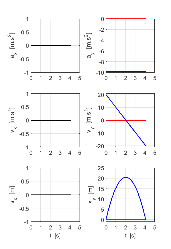
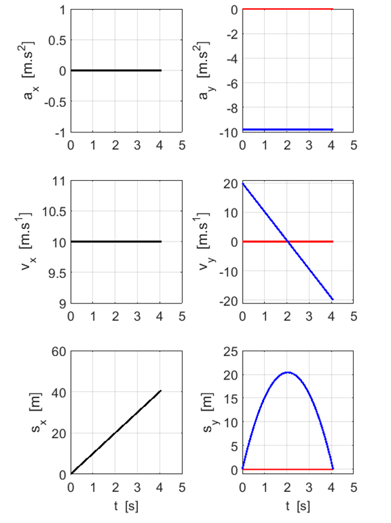
increasing speed. Figure (4) show the variation in the components of the acceleration,
velocity and displacements as functions of time for the truck and cannon ball system in Pat’s frame of reference. The
colour of the line identifies the system (Truck: red and Ball:
blue). If two of the results for the graph are the same, the
colour is shown as black.
Fig.
3. The motion of the truck
and cannon
ball in Pat’s frame of reference. The dots give the
positions of the systems at 0.41 s time intervals. From the spacing of the
dots for the ball,
we conclude that the ball slows down going up and gets faster in falling.
Fig. 4. Time evolution for the motion of
the truck
and ball
in the frame of reference of Pat. Red lines for truck.
Blue lines for ball. Black lines: tuck and
ball have same values for the motion. Calculations
in Pat’s frame of reference Truck The truck remains stationary
The
truck does not move, therefore, the above values for the truck do not change. Cannon
Ball The ball only moves in a vertical direction
along the Y axis. Event
# 1: (
Event
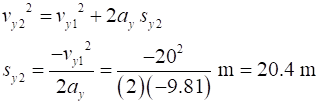
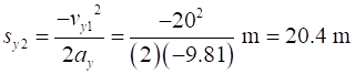
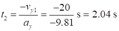
#2 Ball reaches its maximum
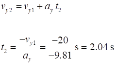
height max height time
to reach maximum height maximum
height We
know that We
know that The ball reaches its maximum height of 20.4 m in
2.04 s. Event
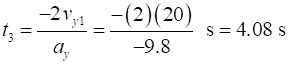
#3 Ball returns to the cannon time
to return to cannon
velocity
of ball to return to cannon The
motion is symmetrical, the time it takes for the ball to fall back into the
cannon is twice the time it takes to teach its maximum height and
the velocity of the ball is We
also can calculate these quantities
The
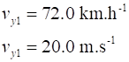
time of flight of the cannon ball is 4.08 s and the velocity at the end of
the flight is 20 m.s-1 in a vertical downward
direction. Chris’s
frame of reference: Initial values
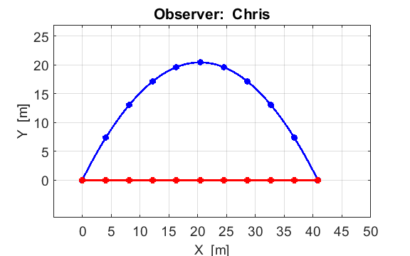
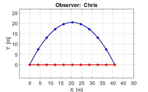
Figure
(5) shows the motion of the truck and the cannon ball from the frame of reference of Chris.
In Chris’s frame of reference the truck moves at a constant velocity
while the ball rises as it slows down and stops at its maximum height and
falls with increasing speed. Figure (6) show the variation in the components of the acceleration,
velocity and displacements as functions of time for the truck and cannon ball system in Chris’s frame of reference. The
colour of the line identifies the system (Truck: red and Ball:
blue). If two of the results for the graph are the same, the
colour is shown as black.
Fig.
5. The motion of the truck
and cannon
ball in Chris’s frame of reference. The dots give the
positions of the systems at 0.41 s time intervals. From the spacing of the dots for the ball, we conclude that the ball slows down
going up and gets faster in falling. The trajectory of the ball is a parabola.
The spacing of the red dots are uniform,
therefore, the speed of the truck is uniform (constant).
Fig. 6. Time evolution for the motion of
the truck
and ball
in the frame of reference of Chris. Red lines for
truck. Blue lines for ball. Black
lines: tuck and ball have same values for the motion. For the ball,
the Calculations
in Chris’s frame of reference Cannon
Ball Event
# 1: (
Event
#2 Ball reaches its maximum height max height time
to reach maximum height maximum
height We
know that
We
know that
The ball reaches its maximum height of 20.4 m in
2.04 s. Event
#3 Ball returns to the cannon time
to return to cannon
velocity
of ball to return to cannon The
motion is symmetrical, the time it takes for the ball to fall back into the
cannon is twice the time it takes to teach its maximum height and
the velocity of the ball is We
also can calculate these quantities
The
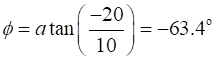
final velocity of the ball is
In
the +X direction the ball moves with a constant velocity of
10 m.s-1. The X displacement of the ball during the flight is Truck The truck moves
with a constant
velocity which is the same
as the ball. therefore, the ball is always vertically
above the truck. At the end of the flight of the ball will land back into the
mouth of the cannon. Figure (3) and figure (6) shows the paths of the cannon ball relative
to Pat and Chris as observers. Both agree the ball goes up and back down
again.
Fig.
3. The trajectory of the cannon ball and truck from Pat’s frame of reference.
Fig.
6. The trajectory of the cannon ball and truck from Chris’s frame of reference We can see from figure (3) and figure (6) that both Pat and Chris are
correct in describing the trajectory of the ball. Pat see the ball rise and fall only in
a vertical direction, however, Chris see a parabolic trajectory for the ball. Motion is a relative concept and depends upon the motion of an observer |
||||||||||||||||||||||||||||||||||||||||||||||||||||||||||||||||||||||||||||||||||||||||||||||||||||||||||||||||||||||


