|
|
WAVES REFLECTION REFRACTION |
|
|
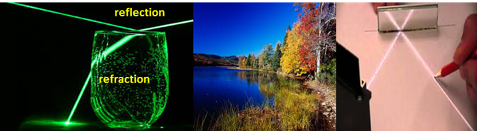
REFLECTION and
REFRACTION If a wave meets a discontinuity where there is
a change in speed in going from one medium to another, the energy carried by
the wave will be reflected backed into the first medium and transferred into
the second medium. The original wave is known as the incident wave. At the discontinuity a reflected
wave and a transmitted
wave (refracted wave) are formed.
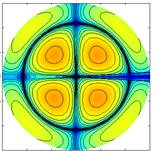
Figure 1 shows a set of simulations for the
propagation of surface water waves.
Fig. 1a. Propagation of a [2D]
wave in a uniform medium with no discontinuties.
Fig 1b. Propagation of a [2D]
wave encountering a discontinuity (normal incidentce). Only
the incident and refracted waves are shown.
Fig 1c. Propagation of a [2D]
wave encountering a discontinuity (oblique incidence). Only
the incident and refracted waves are shown. The
refracted wave propagates in a different direction to
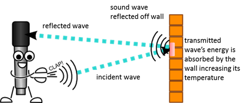
the incident wave. A good example of reflection of sound is an echo. The fraction of energy carried by the echo can be almost as large as
the energy of the incident wave if the surface is rigid and smooth.
Fig. 2. The reflection of a
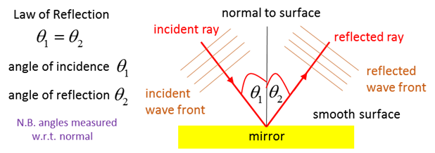
sound wave can produce an echo. From smooth surfaces, waves are reflected
such that the angle of incidence (1) The Law of Refraction applies to sound, light and
all other forms of waves.
Fig.
3. Reflection from a smooth surface. |
||

|
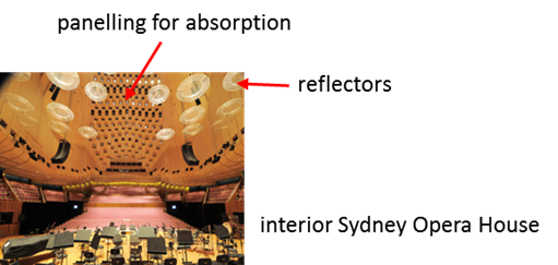
In a room with very reflective surfaces,
sounds can become garbled. When sounds undergo multiple reflections, and
persist after the sound has ceased emitting, we hear reverberations.
If the surfaces are too absorbent, the sound level will be low and sounds
will be dull and lifeless. In the design of concert halls, a balance must be
achieved between reverberation and absorption. Highly reflective surfaces are
often used to direct sound from the stage to the audience.
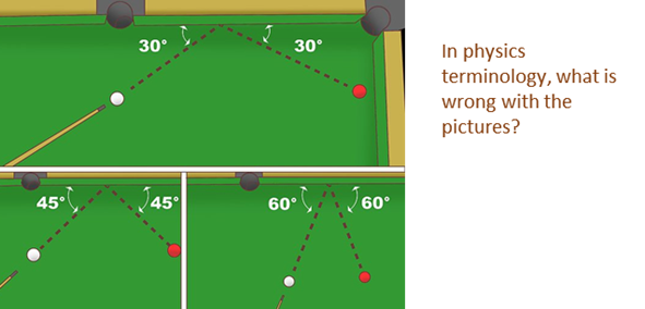
The Law of Reflection is also obeyed by
particles reflected off straight smooth surfaces.
|
|
LAW OF REFRACTION When any
[2D] or [3D] wave traveling in one medium crosses a boundary into a medium where
its velocity is different, the transmitted wave may move on in a different
direction to the original the incident wave as shown in figure 1. This
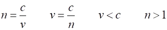
phenomenon is called refraction. The
refractive index (2)
For
electromagnetic radiation, the speed of light in a vacuum is always given by
the symbol (3) light The
direction of propagation of a wave is given by a straight arrow called a ray.
The ray is drawn at right angles to the wavefront of the wave. The angles
measured between the ray and the normal of the discontinuity define the
angles of incidence, reflection and refraction. Incident
wave (medium 1) refractive index Reflected
wave (medium 1) refractive index Refracted
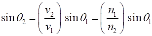
wave (medium2) refractive index The
direction in which the refracted ray travels is determined by Snells Law (4) and for the reflection (1)
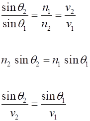
Fig. 4.
Reflection and refraction at a discontinuity. When a wave travels into a medium of greater
refractive index, the wave slows down and bends towards the normal. A
wave that travels into a medium of smaller refractive index,
speeds up and the wave will bend away from the normal. If the velocity
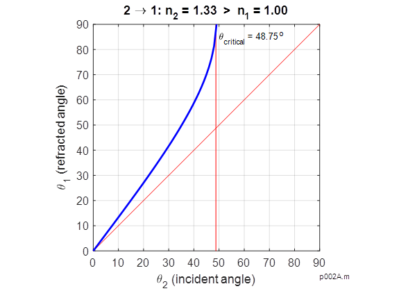
increases, the refracted angle increases, and vice versa. When
a wave passes into a medium of lower refractive index, the light bends away
from the normal. At a particular angle, the angle of refraction will be 90o
and the refracted ray would skim the surface. The incident angle at which
this occurs is called the critical angle
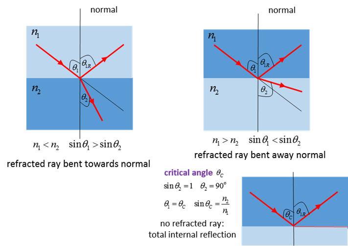
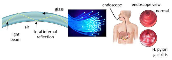
Fig. 5. total internal
reflection with tiny fibres makes it possible
to transmit light in complex paths with minimal loss. |

|
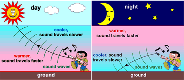
Sound waves propagating through air are bent and
undergo refraction
when the air temperature varies (the higher the temperature, the greater the
speed of sound). On a warm day, the air near the ground may be appreciably
warmer than the rest of the air, so the speed of sound near the ground is
greater. The sound will be refracted and bent away from the ground resulting
in sound that does not seem to travel as far.
At night, the ground is cold and the speed of sound is less than the
speed further above the ground, resulting in the sound being bent towards the
ground. Sounds can be heard over considerably longer distances. N.B.
refraction is caused by difference in the speed of propagation of waves
(figure 6).
Fig. 6. Refraction of sound
waves. Sound waves are bend in air
of uneven temperatures. We hear thunder when the lightning is
close to us, but we often do not hear the thunder for distant lightning
because of refraction sounds travel slower at higher altitudes and bends
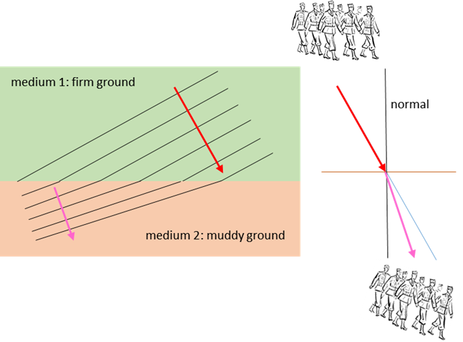
away from the ground, so that we may not hear the thunder clap. Refraction leads to a bending of the
wavefronts when entering a new medium where the speed of the wave is
different. To see why more clearly, we can consider a solder analogy as shown
in figure 7. The solders are marching from firm ground (medium 1) into a
muddy region (medium 2). The solders that reach the mud first are slowed down
first and the row of solders bend. Look at figure 6 again in warmer air,
part of the wavefront moves faster than in colder air, so the bending of the
wavefront is either away or towards the ground.
Fig. 7. Refraction: marching
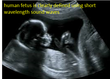
solders analogy. The multiple reflections and refractions
of ultrasonic waves are used by doctors for generating images inside our
bodies. When high frequency (short wavelength) ultrasound enters the body, it
reflects more strongly from the outside of an organ than from its interior,
and an image of the organ is obtained.
Fig. 8. Image of a fetus using short wavelength ultrasonic waves. |
|
Thinking
Question: PREDICT OBSERVE
EXPLAIN The
refracted angle (4) Predict how the refraction angle Predict how the relative intensity of the
reflected and refracted waves change as the parameters are changed. Think
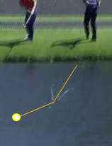
about a golf ball or a stone skipping across the surface of water.
Maximum value of Observe Computer
Simulation: Reflection and Refraction Explain any discrepancies. |
|
Exercise Examine the animations show in figure 1
carefully. From the animations, estimate (the dimensions of the square are
100 m x 100 m):
Period and
frequency of the incident waves and refracted waves.
Wavelengths of
incident waves and reflected waves.
The speed of the
incident waves and reflected waves.
The relative
refractive indices for the two media.
For oblique
incidence, the angles of incidence and refraction. Check your answers using
Snells Law. Hint: use a sheet of thin paper to help make your measurements off the screen. |
|
Exercise Carefully view the graphs and animations
below. Make a list of the terms, concepts and physical principles illustrated
in the figures.
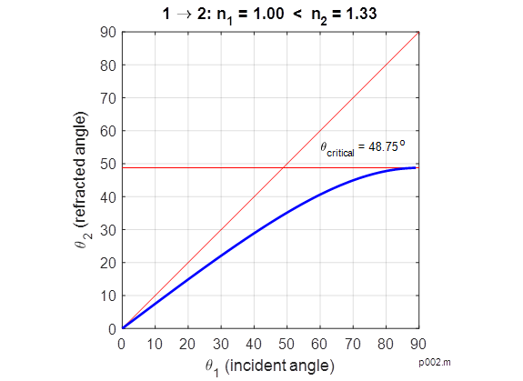
Propagation
of light from a medium of lower refractive index to a medium of higher
refractive index
Propagation of light from a medium of higher
refractive index to a medium of lower refractive index |
|
Animation
produced with wm_refraction01.m
wm_refraction02.m p002.m p002A.m If you have any feedback, comments, suggestions or corrections please email: Ian
Cooper matlabvisualphysics@gmail.com |