|
|
WAVES: RAY MODEL OF
LIGHT IMAGE FORMATION: THIN
LENSES |
|
|
|
||
|
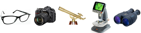
The most important simple optical device is no doubt is the thin lens. Lenses are used in eyeglasses, camera, telescopes, microscopes, binoculars, and many specialized optical instruments.
Fig. 1. Optical devises using lenses.
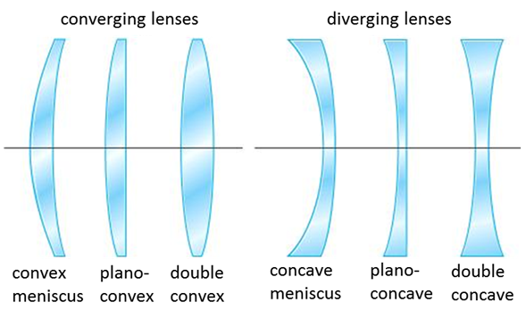
A thin lens is usually circular in cross-section and has two faces which are portions of spherical surfaces. Lenses can be classified as converging or diverging (figure 2). The two faces of thin lenses can be any combination of convex, plane or concave shaped surfaces. The
important property of lenses is that they form images of objects.
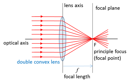
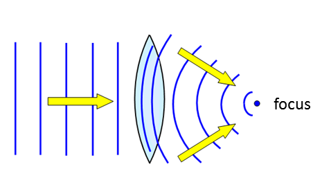
Fig. 2. Different types of converging and diverging lenses. CONVERGING THIN LENSES A converging lens can be used to focus a parallel beam of light on to a spot on the focal plane called a focal (focus) point as shown in figure 12. The distance from the axis of the lens to the focal plane is called the focal length f of the lens.
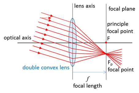
Fig. 3. Rays parallel to the optical axis are focused at a point called the principle focus or principle focal point. Other sets of parallel rays are bought to a focus along the focal plane. N.B. The ray through the centre of the lens does not deviate. It is easy to find the location of an image of an object for a converging lens using a ray tracing diagram. Select two points on the object the top and bottom. Only two rays are necessary from each point to give the image location, but the three most useful rays often used are: 1. A ray drawn parallel to the optical axis from the object will be deviated by the lens so it passes through the principle focal point in the focal plane. 2. A ray drawn from the object passing through the centre of the lens has zero deviation. 3. A ray drawn from the object through the principle focal point on the object side of the lens will emerge from the lens parallel to the optical axis. The intersection of these three lines in the object plane will determine the location and characteristics of the image.
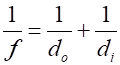
The lens
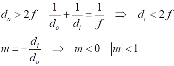
equation for thin lenses relates the focal length (2) If the height of
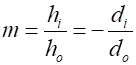
the object is (3) Sign
Conventions
Converging lens
Diverging lens
Object on side of lens light
is coming from
Image on the opposite of the
lens from where the light is coming
Image on the same of the lens
from where the light is coming
Object upright
Image upright
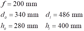
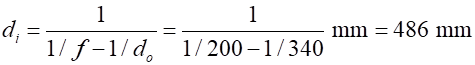
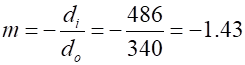
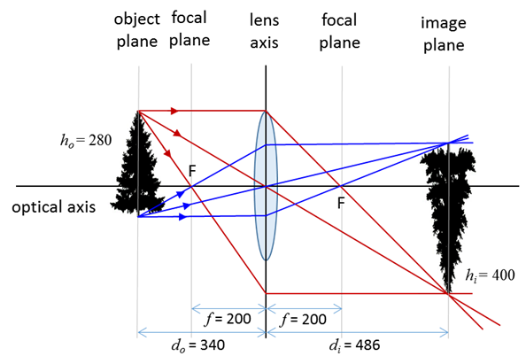
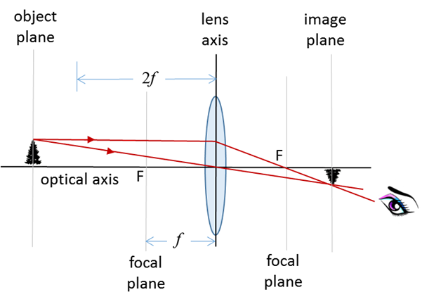
Image inverted Figure 4 show the three rays drawn from the object (tree) to locate the position of the image from the top and from the bottom of the object. The measurements for distances from figure 4 are: From the lens equation (equation 2) the predicted image distance The lateral magnification The predicted height image is inverted
Fig. 4. Ray tracing can be used to estimate the location of the image of an object. Object
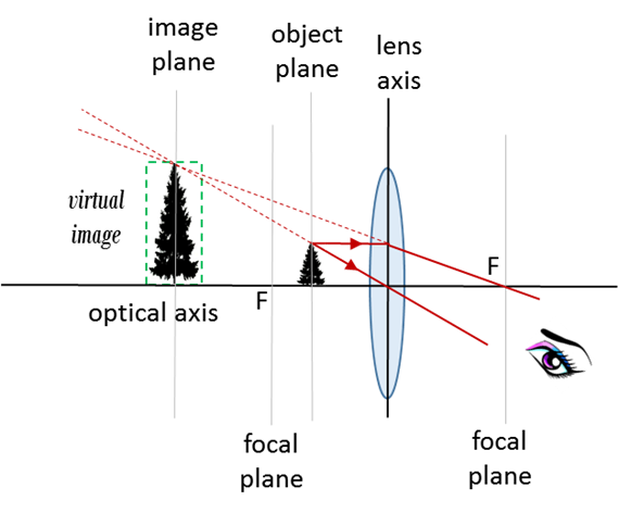
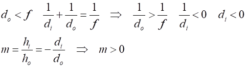
placed within the focal length of the lens
Fig. 5. Simple magnifying glass - object placed within the focal length of a converging lens produces a virtual, upright and magnified image.
Object
placed at the focus of the lens
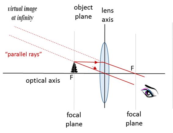
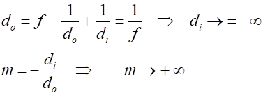
Fig. 6. Object placed in the focal plane. The virtual image is at infinity.
Object
placed at the focus of the lens
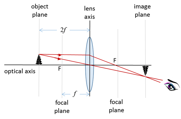
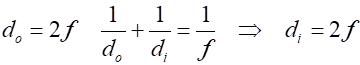
Fig.
7. The object distance is equal to
than twice the focal length Object
at
Fig.
8. The object distance is greater
than twice the focal length
|
||

|
If you have any feedback, comments,
suggestions or corrections please email: Ian Cooper School of Physics University of Sydney ian.cooper@sydney.edu.au |