|
|
WAVES SINGLE SLIT
DIFFRACTION |

|
Diffraction
from single apertures We know that when a wave passes through an
opening, the waves spread in all directions diffraction. However, if we
think about Huygens
Principle, each point in the opening acts like a source of
secondary waves which emit waves that spread out beyond the aperture. So, at
certain points, these secondary waves may be in phase and interfere
constructively, while at other points the waves maybe out of phase and
interfere destructively. Therefore, when a wave passes through an opening a
diffraction pattern maybe produced with distinctive regions of reinforcement
(constructive interference) and regions of cancellation (destructive
interference).
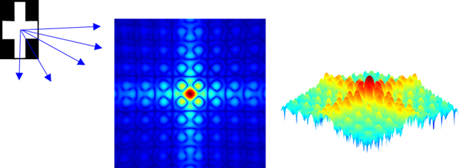
Fig. 1. Light passing through a cross-shaped
aperture spreads and interferes to produce a diffraction pattern on a
distance screen. The diffraction patterns shown correspond to the intensity
of the light on the viewing screen using false colours. Regions of bright and
dark are clearly seen in the plots.
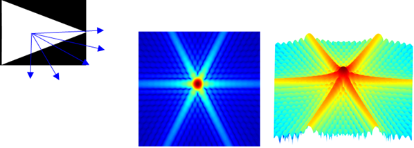
Fig. 2. Light passing through a triangular-shaped
aperture spreads and interferes to produce a diffraction pattern on a
distance screen. The diffraction patterns shown correspond to the intensity
of the light on the viewing screen using false colours. Regions of bright and
dark are clearly seen in the plots.
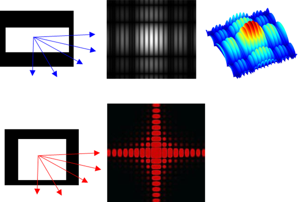
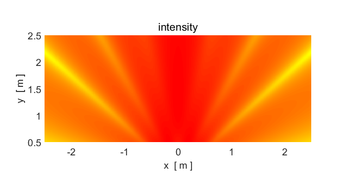
Fig. 3. Light passing through a rectangular-shaped
aperture spreads and interferes to produce a diffraction pattern on a
distance screen. The diffraction patterns shown correspond to the intensity
of the light on the viewing screen using false colours. Regions of bright and
dark are clearly seen in the plots.
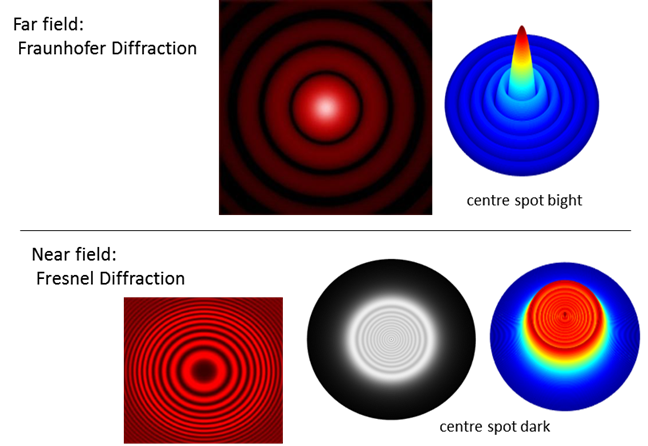
Fig. 4. Light passing through a circular aperture. If the viewing screen is a large distance from the aperture, we get a Fraunhofer diffraction pattern. If the viewing screen is near the aperture, the energy distribution becomes very irregular and unexpectantly, you can observe a dark spot at the centre of the image. This type of diffraction is called Fresnel diffraction. |
|
Diffraction
from a single slit
Animation 1. Diffraction of water waves through an
aperture of width Single slit
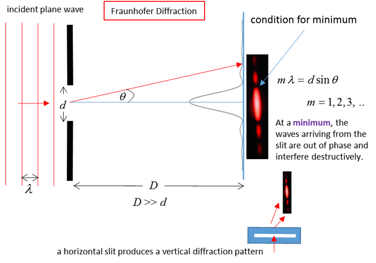
diffraction with visible light Consider
monochromatic light of wavelength
Fig. 6. Single-slit diffraction. When light of
wavelength After
passing the slit, the light is observed on a distant screen xxxxxxxxxx The position of the first order dark fringe
xxxxxxxxxx We know that the sine of angle cant be
greater than 1
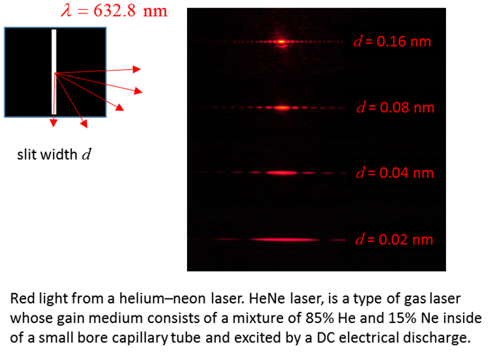
Fig. 7. Red light passing through a narrow slit.
N.B. the smaller the width d of the slit the broader the
diffraction pattern.
Fig. 8. Photographs of the diffraction
for a single slit using green and red lasers. The diffraction pattern shows a strong
central maximum (bright spot) surrounded by secondary maxima of much lower
intensity. The dark fringes are identified by specify their order, m = 1, 2, 3, N.B. the larger the wavelength, the
wider the pattern. |


|
If you have any feedback, comments, suggestions or corrections
please email: Ian Cooper School of
Physics University of Sydney ian.cooper@sydney.edu.au |