|
[1D] FDTD
electromagnetic wave simulations of propagating waves in non-magnetic and
non-lossy dielectric media
INTERFENCE EFFECTS WITH THIN FILMS Ian Cooper Please
email any corrections, comments, suggestions or additions matlabvisualphysics@gmail.com View ELECTROMAGNETISM USING THE FDTD METHOD ft_04.m Download and run the script ft_04.m. Carefully inspect the script to see how the FDTD method is implemented. Many variables can be changed throughout the script, for example, type of excitation signal, boundary conditions, time scales, properties of the medium. We can also model the interference effects on the propagation of EM waves on encounter a thin film. Firstly,
we can consider an EM sinusoidal wave (wavelength The EM
wave will be partially transmitted through the slab and there will be
multiple partial reflections from the front and back of the dielectric slab.
At an interface if the refractive index increases, the reflected wave will
have a
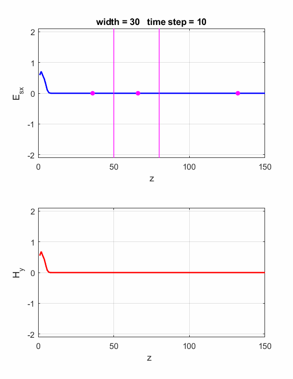
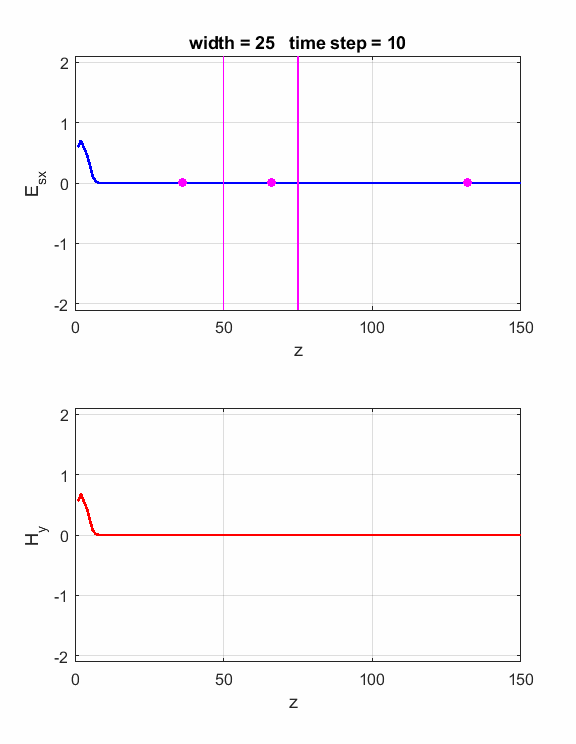
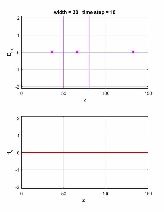
is satisfied, then the waves will interfere constructively (figure 1). If is satisfied, then the waves will interfere destructively (figure 2). The script ft_04.m can be used to model the interference effects of the dielectric slab. Model parameters: Nz = 150 lambda = 80 source: sinusoidal boundary conditions: absorbing eR1 = 1 S1 = 0 eR2 = 4 S2 = 0 dz = lambda / 40 40 Z-grid spacings is equal to one wavelength For eR2 = 4, the refractive index n of the dielectric slab is If Constructive
interference indexR = 50:50+20+10
Destructive
interference indexR = 50:50+20+5
Fig.
1. The width of the dielectric
slab is
Fig.
2. The width of the
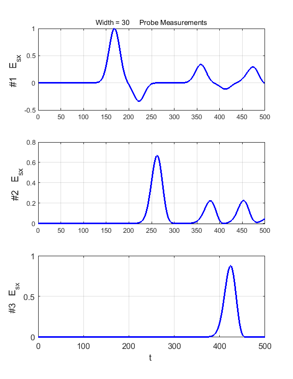
dielectric slab is We can observe the phase changes occurring at the interfaces by using a pulse for the EM wave as shown in figure 3.
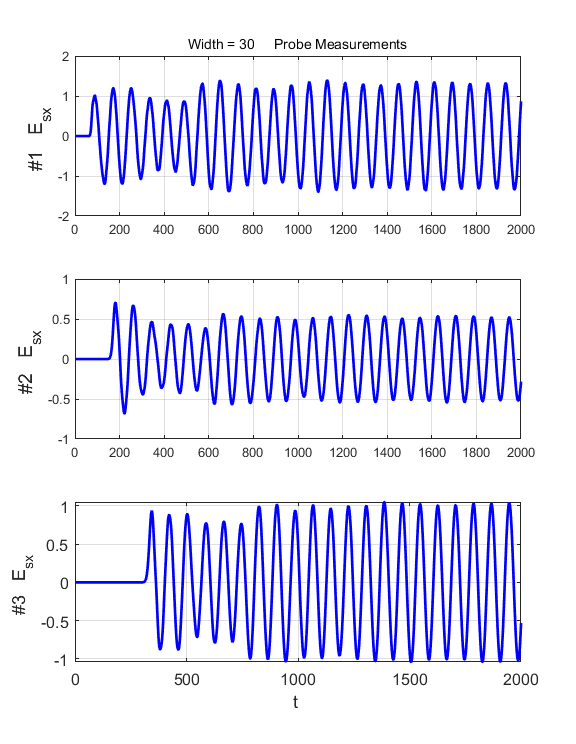
Fig. 3. A pulse striking the dielectric slab. Carefully inspect the electric field as measured by the three probes.
|
|
|