|
COMPUTATIONAL NEUROSCIENCE THE NEURON
MEMBRANE: ION CHANNELS AND GATE VARIABLES Ian Cooper Any comments,
suggestions or corrections, please email me at matlabvisualphysics@gmail.com |
|
MATLAB npHHA.m
bp_neuron_02.m
npIC.m |
|
INTRODUCTION The equations of Hodgkin
and Huxley provide a good description of the electrophysiological
properties of the giant axon of the squid. These equations capture the
essence of spike generation by sodium and potassium ion channels. The basic
mechanism of generating action potentials is a short in influx of sodium ions
that is followed by an efflux of potassium ions. Cortical neurons in
vertebrates, however, exhibit a much richer repertoire of
electrophysiological properties than the squid axon studied by Hodgkin and
Huxley. These
properties are mostly due to a larger variety of different ion channels. In biophysically based neural modelling, the
electrical properties of a neuron are represented in terms of an electrical
equivalent circuit. Capacitors are used to model the charge storage capacity of
the membranes (a
semipermeable cell membrane separates the interior of the cell from the
extracellular liquid and acts as a capacitor). Resistors are used to model the various types of
ion channels embedded in the membrane, and batteries are used to represent
the electrochemical potentials established by differing intracellular and
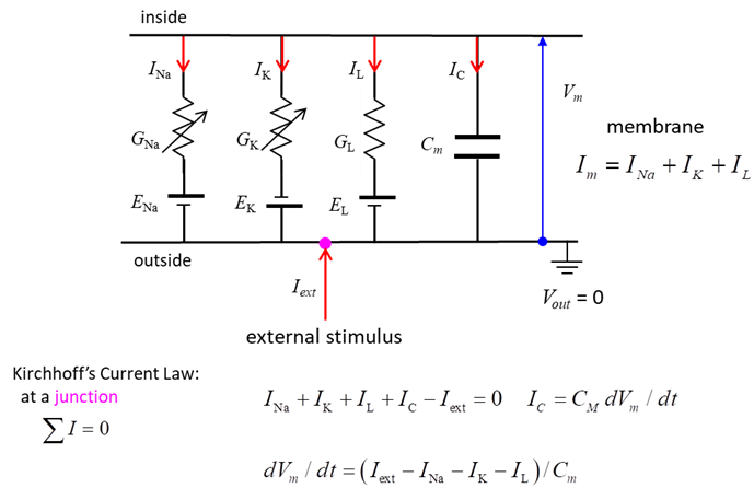
extracellular ion concentrations. Figure 1 shows the equivalent circuit used
by Hodgkin and Huxley in modelling a segment of squid giant axon. The current across the membrane has
two major components, one associated with the membrane capacitance and one
associated with the flow of ions through resistive membrane channels. They found three different types of
ion currents: Na+, K+, and a leak current that consists
mainly of Cl- ions. The flow of ions
through a cell membrane of a neuron is controlled by special voltage
dependent ion channels: Na+ ion channel, K+ ion channel
and a leak ion channel for all other ions. The neuron can be stimulated by an
external current Iext injected into the interior of
the neuron.
Fig.1. Hodgkin
– Huxley model: Electrical equivalent circuit for a short segment of
squid giant axon. Capacitor (capacitance Cm of the cell membrane);
Variable resistors (voltage-dependent Na+ and K+ conductances GNa, GK ); fixed resistor (voltage-independent leakage conductance
GL); Batteries (reversal
potentials Na+, K+ , leakage: ENa, EK, EL); Membrane potential V = Vm = Vin - Vout; External
stimulus Iext; Current directions
(arrows: Iext outside ® inside (I < 0), INa,
IK
and IL inside ® outside (I > 0). Electrical potential (voltage) DV, current I (area A, current density
J), resistance R and conductance G are related by the equations
Electrical activity in neurons is sustained
and propagated by ion currents through neuron membranes as shown in figure 1.
Most of these transmembrane currents involve four
ionic species: sodium Na+, potassium K+, calcium Ca2+
and chloride (Cl-). The concentrations
of these ions are different on the inside and outside of a cell. This creates
the electrochemical gradients which are the major driving forces of neural
activity. The extracellular
medium has high concentration of Na+ and Cl-
and a relatively high concentration of Ca2+. The intracellular medium has high concentration of K+
and negatively charged large molecules A-. The cell membrane has
large protein molecules forming ion channels through
which ions (but not A-) can flow according to their
electrochemical gradients. The concentration asymmetry is maintained
through ·
Passive redistribution: The impermeable anions A-
attract more K+ into the cell and repel more Cl-
out of the cell. ·
Active transport: Ions are pumped in and out of
the cell by ionic pumps. For example, the Na+/K+ pump,
which pumps out three Na+ ions for every two K+ ions
pumped. In the Hodgkin
– Huxley model only the movement of the sodium, potassium ions are
considered, all other ions are considered as part of the leak current. ION CHANNELS In this
section we give an overview of some of the ion channels encountered in
different neurons. The basic equation of detailed neuron models is more or
less the same as that of the Hodgkin-Huxley model except that it contains
more types of ion channels. The membrane potential Vm of a neuron is given by (1) where cm
is the membrane capacity per unit area, Jext is the synaptic input current density, and Jc is the current density through ion channel c. As in the Hodgkin-Huxley model, sodium and
potassium currents are described by equations of the form (2) where
(3)
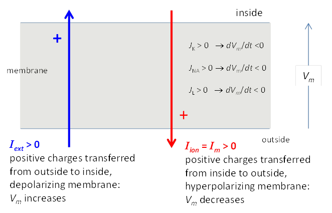
Fig. 2. Sign convention for currents. A
positive external current Iext (outside to
inside) will tend
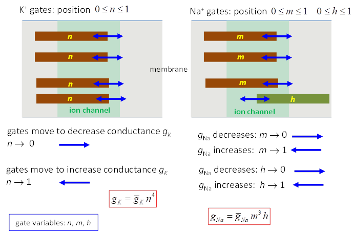
to depolarize the cell (i.e., make Vm more positive) while a positive ionic current Iion will tend to hyperpolarize the cell (i.e., make V = Vm more negative). In a simple model, the Na+ and K+ ions are
considered to flow through ion channels where a series of gates determine the
conductance of the ion channel. The macroscopic conductances of the Hodgkin
& Huxley model arise from the combined effects of a large number of
microscopic ion channels embedded in the membrane. Each individual ion
channel can be thought of as containing one or more physical gates that
regulate the flow of ions through the channel. The variation in g values is determined by the set of gate variables k and h and the number of gates
p and q An activation gate k ® conductance increases with depolarization An inactivation gate h ® conductance decreases with depolarization The Na+
channel is controlled by 3 activation gates and 1 inactivation gate
The K+ channel is controlled by 4n activation gates
The value of the conductance g
depends upon the membrane voltage Vm because the values of n, m and h depend on time, their previous
value at an earlier time and the membrane potential. The resting membrane
potential is given by the symbols Vrest
or Vr.
Fig.
3. Ion channels and gate
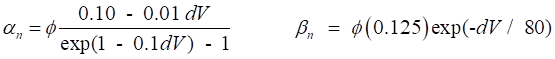
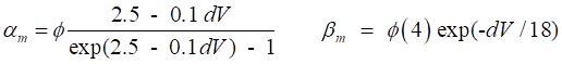
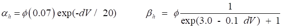
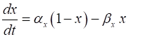
variables for Na+ and K+. The rates of change of the gate variables are
described by the equations (4) where the
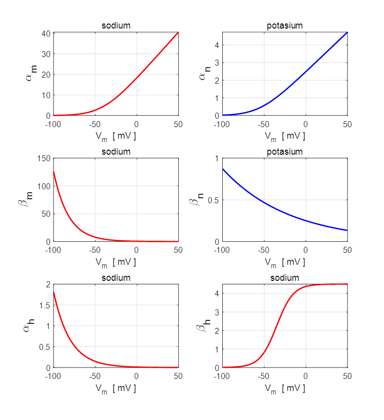
The various functions for
Fig. 4. Plots
of the rate constants (T = 20 oC
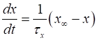
and Vrest = -65 mV). npIC.m In order to getter a better understanding of the
three gating variables ( x = m or n or h) given in equation 4, it is convenient
to rewrite each of the equations in the form
(5A)
(5B)
(5C)
(5D) For a fixed voltage Vm, the variable x approaches the value
Fig. 5. The steady values of (m¥, h¥, n¥) and their corresponding
time constants (tm, th, tn ) as functions of the
membrane potential. The variables m and n are activating gate variables (increase in values
as Vm increases). h is an inactivating gate
variable (h decrease as Vm increases). The
activation of the sodium ion channel (m) for the influx Na+
is much quicker than the response of the out flux of K+ ions (n) or the deactivation of
the sodium ion channels (h) since T =
20 oC and Vrest = -65 mV
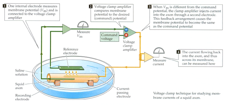
npIC.m VOLTAGE-CLAMP
SIMULATIONS In many of the experiments performed by Hodgkin and
Huxley, they held the membrane at a fixed voltage by inserting an electrode
into the axon of a squid.
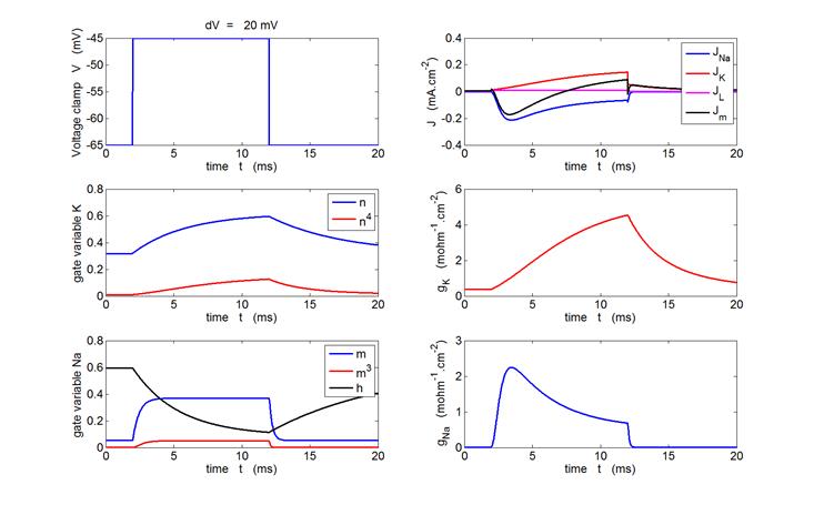
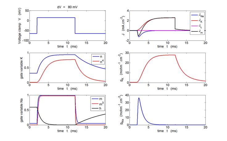
Fig. 6. Voltage-clamp of a squid axon. The Matlab m-script bp_neuron_02.m can be used to calculate
and display the voltage-clamp, the current densities (Jm, JL, JK
and JNa),
the gate variables (m, m3, h and n, n4)
and the conductances (gNa,
gK).
Sample graphical outputs are shown in figure 7 for voltage clamps of +20 mV
and +80 mV. Outline the m-script bp_neuron_02.m structure ·
Default resting potential Vr = -65 mV ·
Voltage clamp is given as a long pulse ·
Rate constants a and b are calculated using the
functions alpha.m and beta.m ·
As the time variable is incremented, the gates variables (n, m,
h) then the conductances (gNa
and gK)
then the current densities (JNA, JNa and JM) are calculated for each time step. The gate
variables are calculated from equation (12) by using the finite difference method to
approximate the first derivative:
Fig. 7.
Variation in the gate variables, conductances and current densities
for a voltage-clamp applied to the axon. The depolarization produced by the
clamp causes a transient increase in Na+ into the cell. The rise
in the K+ current from the cell occurs more slowly and is
maintained as long as the membrane is depolarized. The rate of rise of the
Na+ and K+ currents increases with increasing size of the voltage clamp and
the peak values of Na+ and K+ currents are
significantly increased as the clamp voltage is increased, the peak values
are over 100 times the magnitudes in the resting membrane. bp_neuron_02.m |